
Inspection Jig User Manual
Detailed user manual for the inspection jig, covering normal operation, data reading, function key settings, and sensor calibration.
Detailed user manual for the inspection jig, covering normal operation, data reading, function key settings, and sensor calibration.
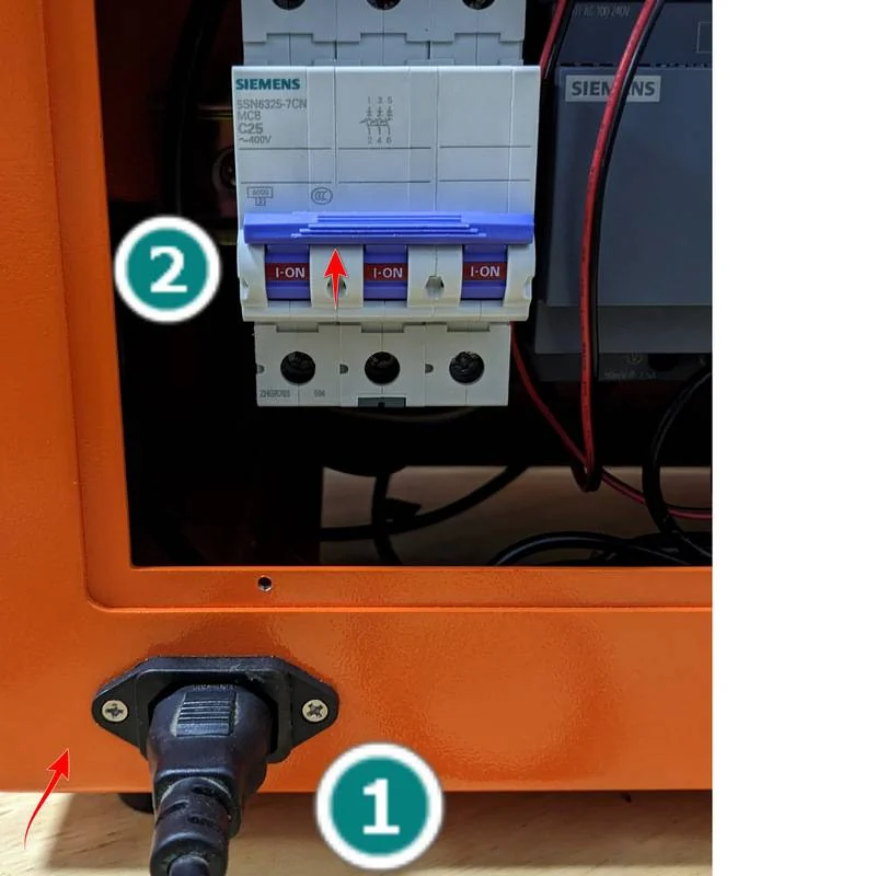
Power On — Input Voltage: 220V
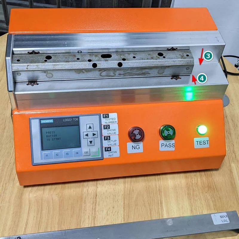
Place the inspection workpiece, ensuring the bottom is flat and the back is against the positioning block.
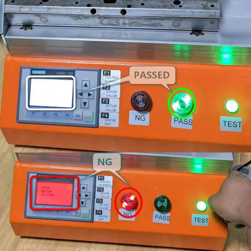
Press the green button to inspect. Two possible results: Pass or NG. The corresponding count will update.
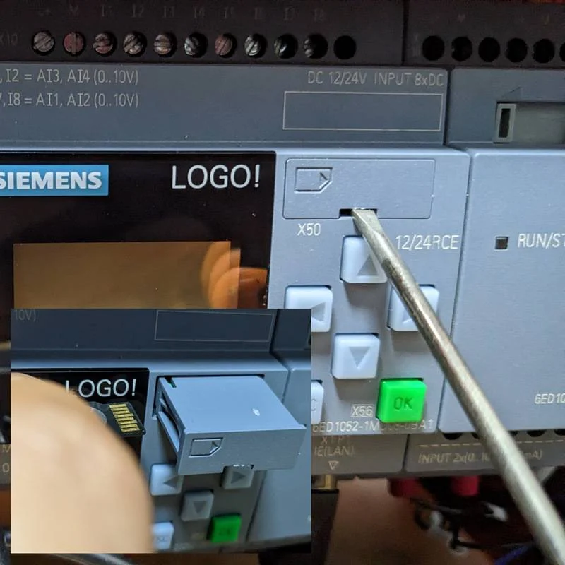
Open the back cover of the jig; use a flathead screwdriver to pop out the SD card.
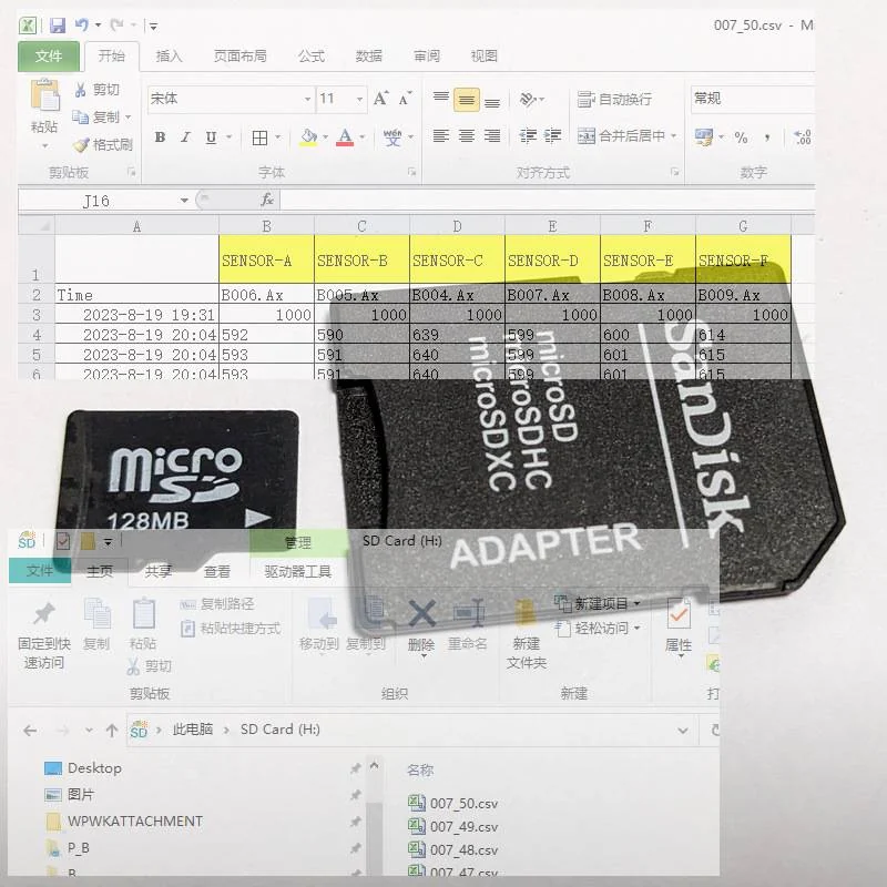
Read data from the SD card, open the CSV file with Excel. Refer to the yellow rows in Excel for sensor position and column mapping.
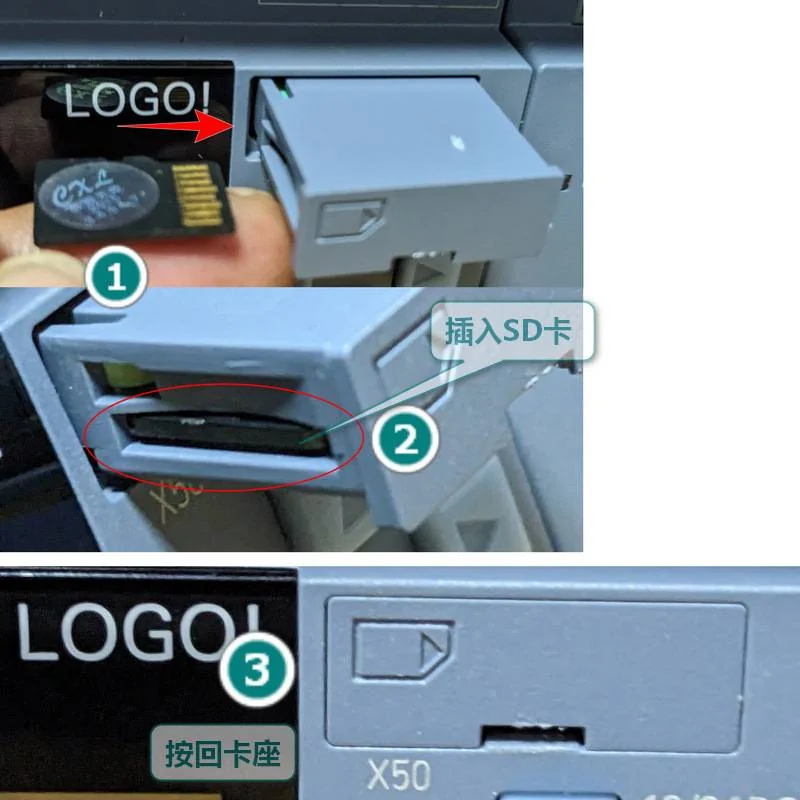
Reinsert the SD card and verify it is working properly. Diagnostics -> Hardware -> SD Card
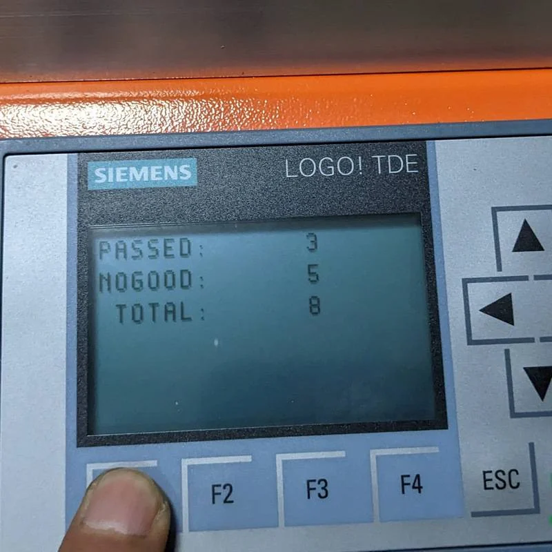
Display test counts: PASSED: xx, NOGOOD: xx, TOTAL: xx.
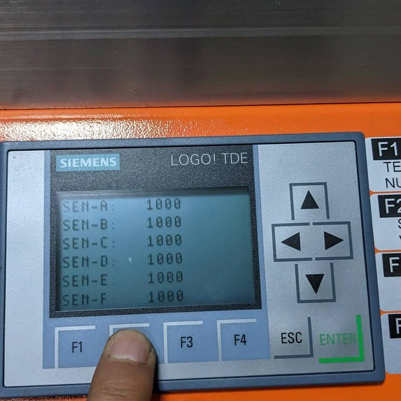
Display current sensor value, range: 0-1000. If no workpiece is placed, value is 1000.
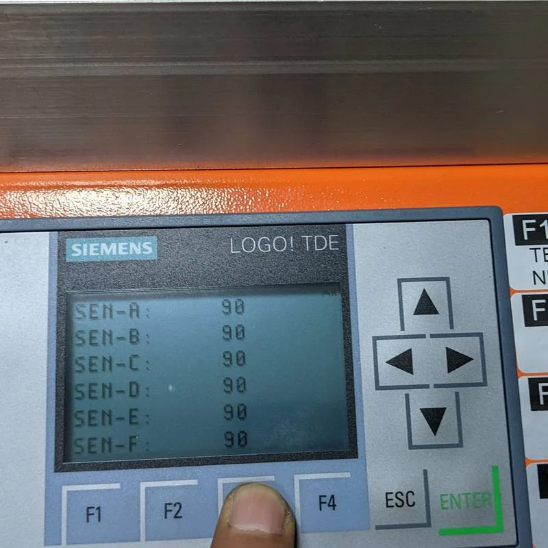
Set range value, +/-0.15 distance, recommended value: 90
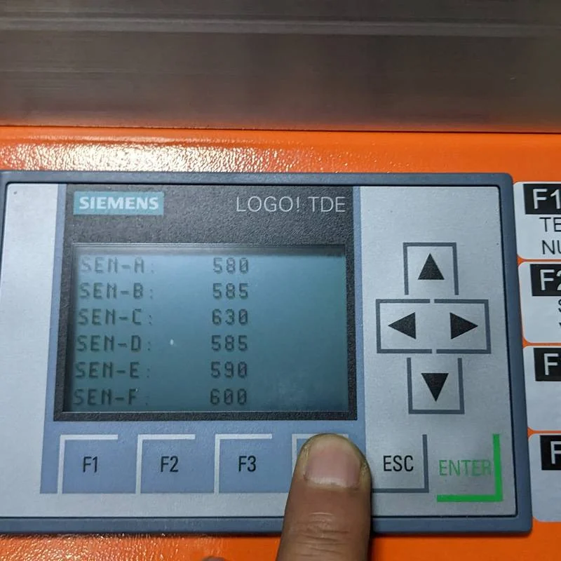
Minimum threshold value, range: 500-700
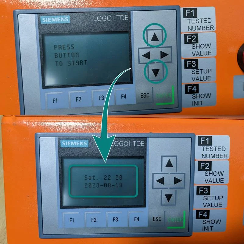
1. Enter Settings: press up/down keys until Time: Sat. 22 20 and Date: 2023-08-09 appears.
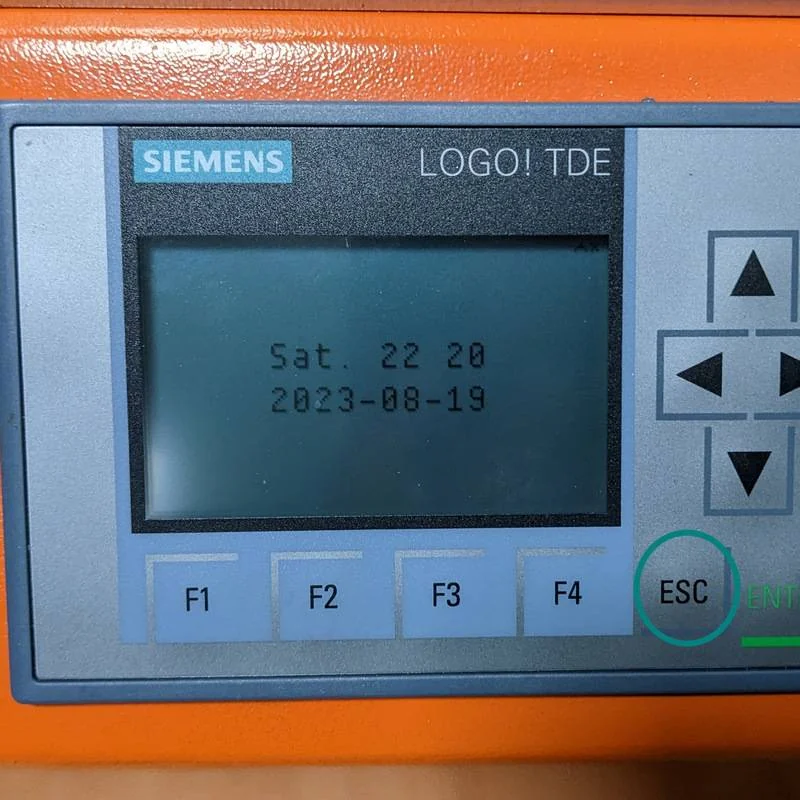
2. Press ESC to enter settings. Do not change unspecified items.
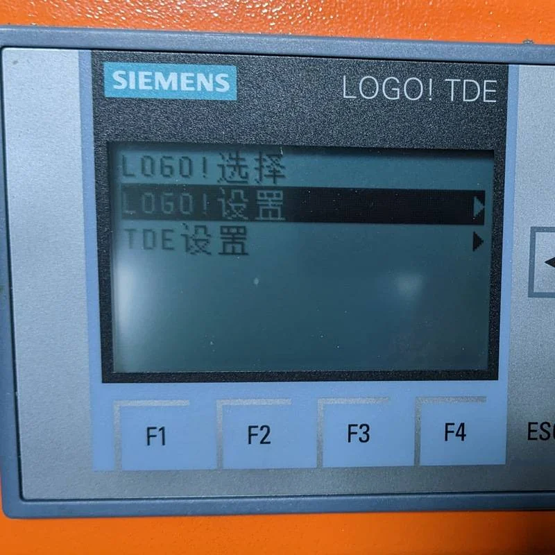
3. Set Sensors LOGO! Settings -> Programming -> Set Parameters
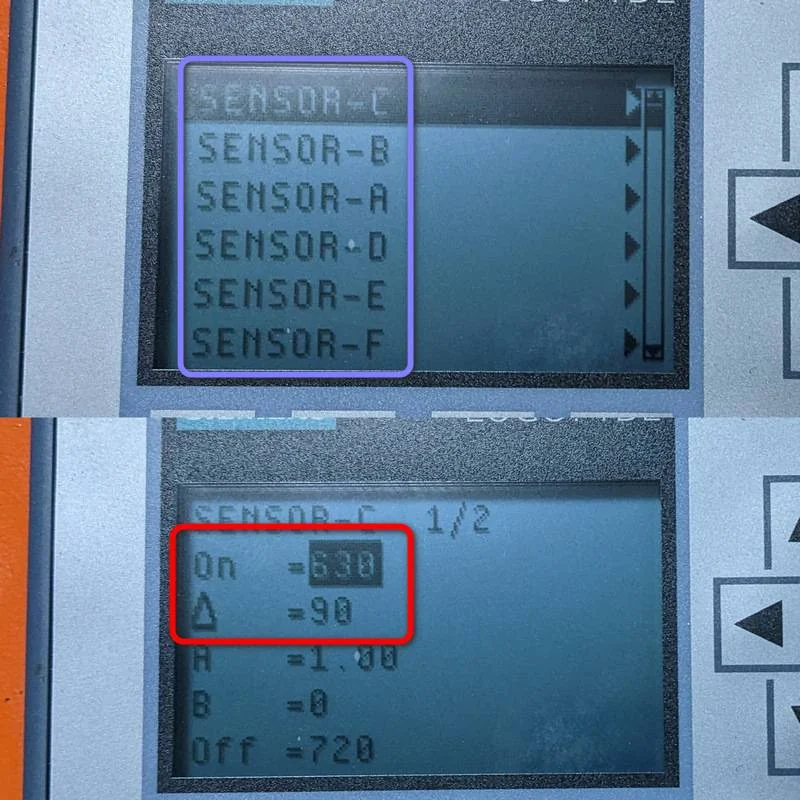
4. Setting Values: only set the On and ∆ values for SENSOR A/B/C/D/E/F. Do not change other values.
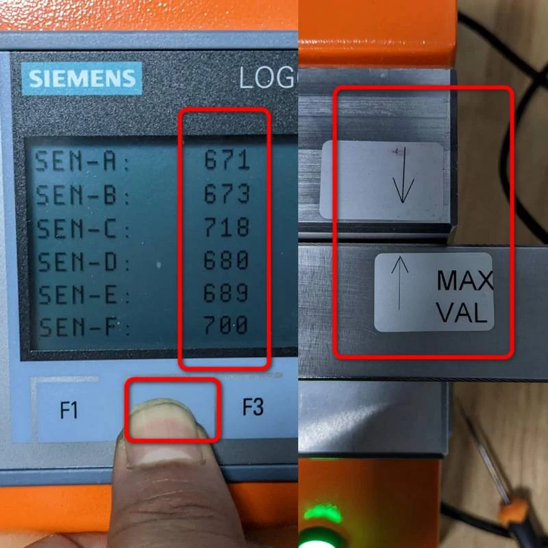
1. Find Minimum Value: place the standard block, align to MinValue, press F2.
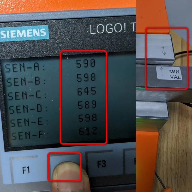
2. Find Maximum Value: place the standard block, align to MaxValue, press F2.
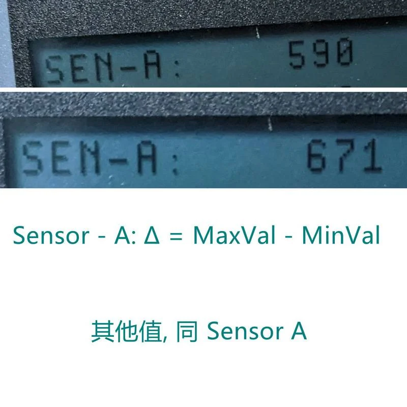
3. Calculate ∆: ∆ = MaxValue – MinValue
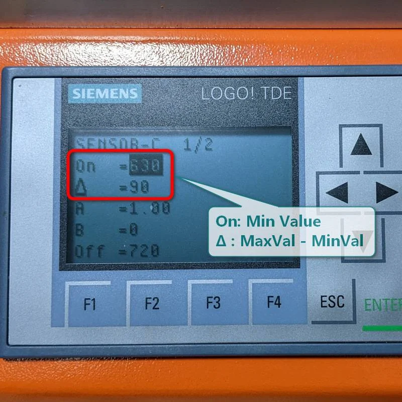
4. Setting Values: refer to the steps above to set each sensor's On (MinValue) and Delta (∆).
Good: LOGO! Settings -> Programming -> Set Parameters -> PASS_WP_NUM -> Cnt (set desired value)
Defective: LOGO! Settings -> Programming -> Set Parameters -> NG_WP_NUM -> Cnt (set desired value)